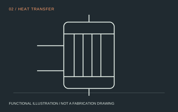
Vertical tube bundle for falling-film evaporation
Transfer heat through a continuously wetted surface.
02 / HEAT TRANSFER
The product travels down the inner tube wall while heat crosses from the shell side. The liquid flow decreases as water evaporates. An apparently adequate inlet flow can become an inadequate film further down the concentration path.
Enquire about this modulePosition in the system
| Input | Output | Installation interfaces |
|---|---|---|
| Distributed liquid and heating medium on separate sides | More concentrated film plus generated water vapour | Product head, heating-side inlet, condensate drain, separator and support steel |
Specify the engineering conditions
| Review item | Required basis |
|---|---|
| Area and geometry | Obtain the proposed tube length, diameter, pass layout and design duty together. |
| Material selection | Match product acidity, cleaning chemistry and corrosion evidence; do not select alloy from product name alone. |
| Mechanical envelope | Confirm lifting clearance, thermal expansion and maintenance access. |
Operation & maintenance
Trend pressure, temperature, feed and outlet concentration together. A falling heat-transfer rate may reflect deposits, utility changes or poor distribution; investigate the cause before increasing heating temperature.
Selection limit
Area alone is not a capacity rating. Viscosity, boiling point elevation, available temperature difference and fouling allowance belong in the same duty specification.